

InstroDAQ and the same configuration/acquisition code works across different hardware.
Supported Vendors
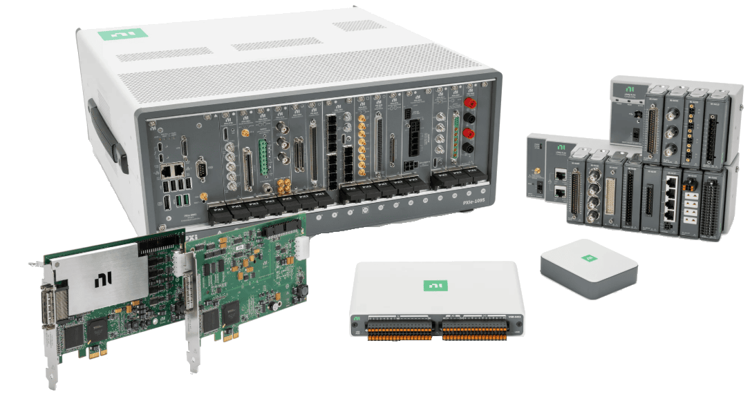
National Instruments
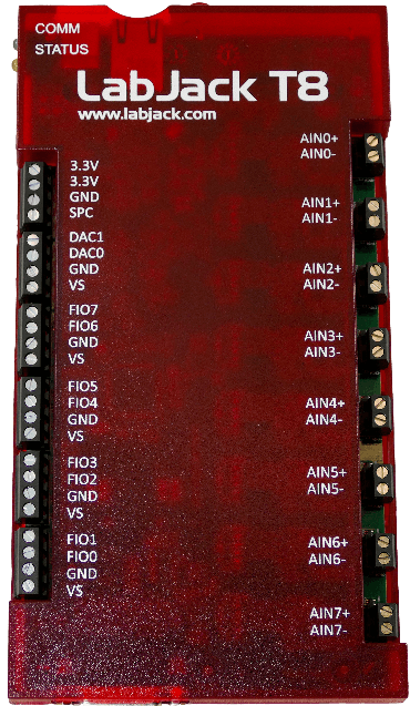
LabJack T-Series
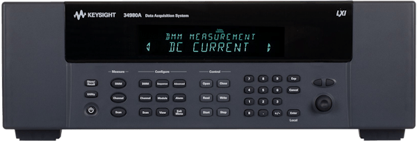
Keysight 34980A
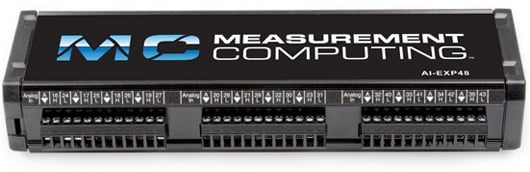
Measurement Computing (MCC)
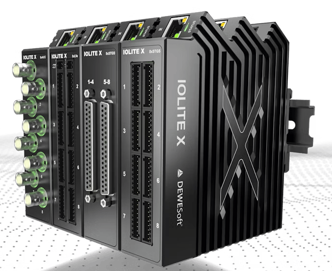
DewesoftX
Key Concepts
Lifecycle Pattern
The typical InstroDAQ workflow follows this pattern:InstroDAQ(name, driver, ...)- Instantiate the DAQ with a vendor driveropen()- Establish connection to the hardware- Configure - Set up , timing, and other settings
start()- Begin acquisition (if using hardware timing or the software-timed daemon)- Acquire data - Read/fetch measurements
stop()- End acquisition (if started)close()- Disconnect from hardware
Channels
InstroDAQ supports both analog and digital I/O:- Analog Input/Output: Measurements and generation with configurable ranges
- Digital Input/Output: Line-based or port-based digital I/O
Aliases
Map vendor-specific physical channel names (e.g., “AIN0”) to logical names (e.g., “temperature_sensor”) Channel aliases are used as channel names when data is published to Nominal Core or Connect.Timing Modes
InstroDAQ supports three acquisition modes: Software-Timed (Manual Polling)- You call
read_analog()when you want a sample - No need to call
start()orstop() - Use case: Low-frequency monitoring, event-driven sampling
- Configure the polling rate with
configure_ai_sw_sample_rate() - Call
start()to launch the background daemon, which callsread_analog()once per period and publishes the results - Use case: Low-frequency continuous monitoring without a hardware sample clock
- Configure sample rate with
configure_ai_hw_sample_rate() - Call
start()to begin background acquisition - Data automatically published via the background daemon, OR manually fetch with
read_analog() - Use case: Mid to high frequency continuous monitoring with deterministic sample timing.
TimingConfigException. To run both against one device, build a separate InstroDAQ per mode with non-overlapping channels: see the NI hardware- and software-timed example.
Creating an InstroDAQ Instance
Construct a vendor driver and pass it toInstroDAQ:
Vendor-Specific Driver Examples
Configuring Channels
Analog Input Channels
Configure analog input channels with measurement range and logical names:The
physical_channel naming convention depends on your DAQ vendor:- NI DAQmx: fully qualified
device/channel, for example “Dev1/ai0”, “Dev1/ai1”. - LabJack: “AIN0”, “AIN1”, etc.
- MCC: Integer channel index as a string, for example
"0","1". - Keysight: Depends on module slot and channel configuration
- DewesoftX: The channel
Nameshown in the DewesoftX channel setup tab, for example"AI 1"
Scalers
It’s common for the data being read by an analog input channel to need scaling to represent a real-world physical phenomenon. For example, a 0-5 volt sensor measuring pressure.InstroDAQ supports adding a Scaler object when you configure your analog channel. The Measurement published and returned by read_analog will contain these scaled values.
Example of a 0-5V pressure sensor that measures 0-3000 psia.
ScalerPipeline scaler.
For example, a thermocouple that’s fed into an amplifier and then the DAQ will require two stages of scaling.
- Scaling out the amplifier to get to the actual voltage seen across the thermocouple terminals.
- Scaling the voltage seen across the thermocouple terminals to temperature.
Scaler and implementing scale and units methods.
Analog Output Channels
Configure analog output channels:The
physical_channel naming convention depends on your DAQ vendor:- NI DAQmx: fully qualified
device/channel, for example “Dev1/ao0”, “Dev1/ao1”. - LabJack: “DAC0”, “DAC1”, etc.
- MCC: Integer channel index as a string, for example
"0","1". - Keysight: Depends on module slot and channel configuration
Digital Channels
Before configuring a digital channel, you need to specify the following parameters to match your application and DAQ hardware:InstroDAQ exposes configure_digital_input and configure_digital_output for a single line, and configure_digital_port for a whole port.
- direction (port only): Use
Direction.INPUTfor digital input orDirection.OUTPUTfor output. The line methods carry the direction in the method name, so they take nodirectionargument. - physical_channel: The physical line or port on your DAQ device (e.g.,
"5101","5101/2"for Keysight, or"FIRSTPORTA","FIRSTPORTA/0"for MCC). This name is vendor-specific. Refer to your device documentation. - logic: Sets whether the channel treats a HIGH or LOW physical level as “True”. This is required for correct logic interpretation.
- logic_level (optional): Specifies the voltage threshold (in volts) used to distinguish HIGH from LOW, if your device supports changing this.
- alias (optional): A logical name for the channel, helpful for clarity and for use with publishers.
- port_width (port only): Port width in bits (8/16/32/64), required by
configure_digital_port.
Typed Channel Configuration
InstroDAQ exposes a measurement-specific configuration method per channel kind. Each builds a typed channel (AnalogVoltageChannel, AnalogCurrentChannel, AnalogThermocoupleChannel, or a DigitalLineChannel) and delegates to a dedicated driver method:
Analog driver support:
Digital driver support:
LabJack thermocouple channels
The LabJack driver registers a thermocouple’sAIN# in the scan list as raw volts and converts each sample to temperature on read with LJM’s TCVoltsToTemp and the devices internal CJC. More info about using thermocouples with a LabJack device can be found here.
cjc_source:
INTERNAL(default): the driver reads the device’s cold-junction sensor alongside the thermocouple. The T8 streams the per-channelTEMPERATURE#sensor, the T7 streams the internal sensor’s raw volts (AIN14), and the T4 snapshotsTEMPERATURE_DEVICE_Kbefore each software-timed read (theTEMPERATURE_DEVICE_Kregister cannot be streamed).CONSTANT: pass the reference junction temperature viacjc_temp, expressed in the channel’sunit.CHANNEL: not yet supported by this driver.
The T4 snapshots CJC once when the stream starts, so its thermocouple readings can drift over a long hardware-timed acquisition.
tc_input_scaler when configuring the channel. The T4’s 12-bit ADC cannot resolve a bare thermocouple, so LabJack recommends using an LJTick-InAmp: the T4 defaults tc_input_scaler to the InAmp’s x51 gain and 1.25 V offset jumpers.
unit is required and is a TC_UNIT member. It governs cjc_temp, range_min/range_max, and the returned readings. A channel scaler applies to the converted temperatures.
MCC thermocouple channels
The MCC Universal Library converts thermocouple readings on the device and returns temperature directly. The driver therefore rejectstc_input_scaler, and cold-junction compensation is always internal: cjc_source must be INTERNAL (the default).
unit; configuring a channel in a different unit raises ValueError. During hardware-timed acquisition an open or overranged thermocouple reads NaN, matching the LabJack driver.
Thermocouple channels on MCC expansion boards (the CIO-EXP and EXP-GP families) are not supported. The driver configures thermocouple channels on the base board only.
Setting the channel type to thermocouple fixes the input range in hardware at plus or minus 125 mV, and the MCC Universal Library exposes no call to change it. range_min and range_max are therefore ignored on MCC thermocouple channels. They do not clip readings and they do not raise. Use unit to control the temperatures the driver returns.
MCC input mode
MCC boards set the analog input mode in one of two ways. Some boards set it per channel. Others set it for the whole board. The driver tries the per-channel call first and falls back to the board-wide call when the device rejects it. MCC hardware has no non-referenced single-ended mode, soTerminalConfig.NRSE raises ValueError.
On board-wide devices every configured channel shares one mode. Configuring several channels with different terminal_config values leaves the board in the mode of the channel configured last. The earlier channels read in that mode too, with no error raised.
DewesoftX channels
TheDewesoftX driver streams live channels from a DewesoftX instance running on the same Windows PC. DewesoftX owns the channel setup, the scaling, and the sample clock, so the driver binds existing channels instead of configuring hardware:
configure_voltage_input,configure_current_input, andconfigure_thermocouple_inputall bind the DewesoftX channel named byphysical_channel. The channel must be set to Used in DewesoftX. Range, terminal, and thermocouple settings are ignored.- Scalers are not supported for configured channels for
DewesoftXbackedInstroDAQs. configure_ai_hw_sample_raterequiressample_rateto be the rate the DewesoftX setup already runs at, and raisesHWTimingExceptionfor any other value, naming the rate to pass.get_actual_sample_rate()returns the rate once timing is configured.- Change the rate in the DewesoftX setup, not through
instro. - Synchronous channels are timestamped from the DewesoftX store start time and the sample count. Asynchronous channels (for example CAN signals) keep their own per-sample timestamps.
- Samples can only be read when a DewesoftX storing session is in progress.
start()attaches to the running storing session.start(start_storing_session=True)starts one, andstop(stop_storing_session=True)ends it. Passdxd_nameto the driver to name the data file DewesoftX stored to during the storing session.
Configure hardware timing, not software timing
configure_ai_sw_sample_rate() is not supported by this driver. Call configure_ai_hw_sample_rate() instead.Hardware timing here means DewesoftX owns the sample clock, not that instro reads the acquisition hardware. Every sample still arrives from the running DewesoftX software.Hardware-Timed Sample Rate
For continuous hardware-timed acquisition, configure the sample rate.samples_per_channel parameter determines how many samples, per channel, are returned on every call to read_analog().
- The lower the
samples_per_channel, the more responsive and lower latency your app will be, but may not be able to keep up with the sample rate. - The ratio of
sample_ratetosamples_per_channeldetermines how often data will be fetched from the DAQ buffer.- Example, if
sample_rateis 1000 andsamples_per_channelis 500, you’ll see 500 sample batches of 1000Hz data twice a second, for every channel.
- Example, if
- The default for
samples_per_channel, if left unset, is dynamically set to enable fetching batches 10 times per second. This is a reasonable balance between reliably keeping up with the data stream and app responsiveness.
A single
InstroDAQ instance carries one analog input sample rate. To run multiple NI DAQmx tasks at different hardware sample rates, create one InstroDAQ instance per task: see the NI multi-rate acquisition example.Software-Timed Sample Rate
For continuous acquisition without a hardware sample clock, configure a software-timed polling rate instead. The background daemon then pacesread_analog() calls at 1 / sample_rate.
Analog Input
Software-Timed Acquisition (Manual Polling)
For manual, on-demand sampling, configure the input channels and callread_analog() in your own loop. See DAQ read analog SW timed without a background daemon.
The read_analog() method returns a Measurement object (or list of Measurement objects for multiple channels) containing:
channel_data: Dictionary mapping channel aliases to lists of valuestimestamps: List of timestamps (nanoseconds since epoch)values: Property returning all values as a list (convenience for single-channel reads)latest: Property returning the most recent value (convenience for single-channel reads)
Software-Timed Acquisition with the Background Daemon
For continuous software-timed acquisition, configure a polling rate withconfigure_ai_sw_sample_rate() and start() the background daemon. The daemon calls read_analog() once per period and publishes the results.
While the daemon is running, read() and read_batch() serve analog channels from the acquisition the daemon just completed, so the same read code works whether or not the daemon is running. Both block until the next acquisition arrives, so a read returns new samples instead of the last cached value. read_analog() raises instead: the daemon owns the hardware reads. Call get_channel() to read the channel buffer, which keeps per-channel sample history and the daemon’s own timing channels. See the software-timed example.
Hardware-Timed Acquisition with Background Fetching
See Two ways to get data for more information regarding background fetching of measurements. For continuous high-speed acquisition, program the sample clock withconfigure_ai_hw_sample_rate(), then start() the background daemon and pull samples with get_channel(). See DAQ read analog HW timed.
In this mode:
start()begins hardware-timed acquisition in the background daemonstop()ends the background acquisition
Important Note about PublishersData is published as a direct result of an instrument method being called.For example, when you call
read_analog(), this not only returns the DAQ data but also causes all attached Publishers to publish the measurements automatically.Therefore the background daemon, which is calling instrument methods, is publishing the data!Hardware-Timed Acquisition with Manual Fetching
For hardware-timed acquisition where you control when to fetch buffered data, callstart(background=False) to fill the hardware buffer without spinning the background daemon, then call read_analog() yourself. See DAQ read analog HW timed without a background daemon.
With start(background=False), calling read_analog() during hardware-timed acquisition fetches from the hardware buffer rather than triggering a new conversion.
Analog Output
Software-Timed Generation
For manual, on-demand updates of set points, configure the output channels withconfigure_voltage_output() and call write_analog_value(). See DAQ write analog SW timed.
Digital I/O
Reading Digital Lines
Writing Digital Lines
Reading and Writing Digital Ports
For devices that expose digital I/O as parallel ports (multiple lines read or written together), useread_digital_port() and write_digital_port(). Configure the channel with a port_width that matches the hardware port, then read or write the full port as a single integer value.
Port-based I/O is implemented for MCC, NI DAQmx, and Keysight devices. On LabJack,
write_digital_port() and read_digital_port() raise NotImplementedError; use write_digital_line() / read_digital_line() to address individual lines instead. Keysight groups a single port into one channel of at most 32 bits, so DigitalPortWidth.WIDTH_64 is rejected — configure a 64-bit span as two channels. On NI DAQmx, port_width is checked against the port’s physical line count and a mismatch raises ValueError — pass the DigitalPortWidth that matches the hardware port.Unified Read and Write
Reading by Alias
read() accepts a single alias and returns that channel’s Measurement. read_batch() accepts a list of aliases, or None for every configured input channel, and returns a dict keyed by alias, with each value the channel’s Measurement. Analog aliases are served from one batched analog read; digital aliases are read per line or port.
While the background daemon is running, analog aliases are served from the acquisition the daemon just completed instead of triggering a hardware read. The call blocks until the next acquisition arrives, and every alias comes from that same acquisition, so channels never span batches. One acquisition carries samples_per_channel samples per alias when hardware timing is configured, or one sample per alias when software timing is configured. The wait times out at two acquisition durations, with a floor of 10 seconds, so a slow acquisition does not time out. Call get_channel() when you need sample history, a specific sample count, or a read that does not block.
Writing by Alias
write() writes a single value to a single alias and returns the resulting Command. write_batch() writes values[i] to channels[i] and returns a list of Command objects. Both route each alias to analog or digital output by channel type.
By default, the first write that fails at the device logs a warning and raises RuntimeError naming the failed channel; later channels in the batch are not written. Pass continue_on_failed_write=True to log the failure and continue with the remaining channels instead; the returned list then contains only the successful commands. Every write emits a per-channel log line: <alias> -> succeeded at debug level, or <alias> -> failed: <reason> at warning level.
float, int, or bool, and every channel and value is validated before anything is written: each alias must be configured as an output channel (unknown aliases raise KeyError), aliases may appear only once per batch, analog outputs require a finite number within the channel’s configured range_min/range_max, digital lines require 0 or 1 (in any of the three forms), and digital ports require an integer. An invalid value, a duplicate alias, or a channels/values length mismatch raises ValueError with no channels written. Digital values are coerced to int. Relays are not routed through write(); use open_relay() and close_relay().
Example
More examples found in ExamplesDeprecated methods
TheseInstroDAQ methods still work, and each emits a DeprecationWarning naming its replacement. They are scheduled for removal in a future release.
Custom driver authors:
configure_ai_channel and configure_ao_channel are deprecated on DAQDriverBase for the same reason. Implement configure_ai_voltage_channel and configure_ao_voltage_channel instead.